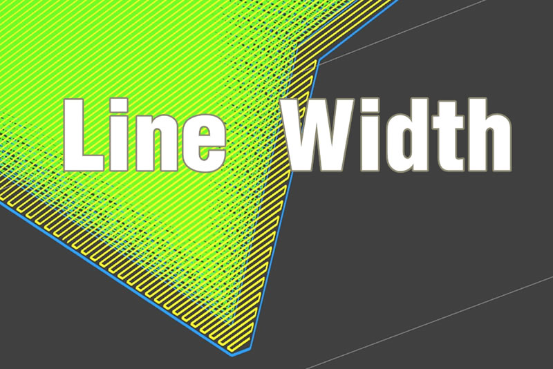
I believe that sooner or later you will encounter such problem, there are small gaps in the surface of the prints, even if it does not affect anything, but people obsessive about details will not be comfortable seeing these “defects”.

So how to improve the print surface quality? One answer is to adjust the “line width” parameter.
In order to be make it clear for you to understand how line width will affect print surface, here we did a small, far from comprehensive, study on the effects of line width on print quality.
First, what is the line width? Line width is actually the setting that determines the width of the tool path during printing.

It will change the pattern of infill and the top surface of prints, therefore affect the print quality in terms of dimensional accuracy and surface quality.

Material and Method
- Top surface quality test. We made a series of 10 thin walls with thickness from 1.5mm to 3.75mm. Then different line width settings were used to print the thin walls.
- We made a model with holes with diameters of 25mm, 18mm, 8mm. Then we print them with line width of 0.35mm, 0.5mm and 0.75mm.
Results
- Top surface quality under different line widths and feature thickness.


Discussion

When I first knew that I could adjust the print quality by setting the line width, I thought about the ice cream production process. . .( Yes, more Please. ). When the system changes to different line width, the extrusion amount and print head movement speed will adjust accordingly. You may imagine that the print head will move faster and extrusions will become slower when the machine try to achieve a thinner line width. Of course, the actual tool path will be different when the parameter changes, thinner line width will result in the increase of tool path total length and print time.
So the extrusion width is thicker the better or vice versa??

Next, let’s analyze the contents of the form. When the line width is adjusted to 0.35mm, we can see that the printing effect is basically great, but when the thickness is 2mm and 2.25mm, the fineness of printing is not as good as the line width of 0.7mm.
When the line width is set to 0.4mm,thickness of 3.25mm and 3.5mm are good. The line width is set to 0.5mm, it prints the most complete model fill with a thickness of 1.5mm.
So there is no definite answer and it depend on your model case by case. We here provide a quick glimpse on how the line width setting will affect features with different thickness.
Please remember following factors will also affect top surface quality but not in the scope of today’s discussion:
- The orientation of the print
- Nozzle diameter
- Print speed

Finally, we tested when the layer thickness is 0.2mm, the default value of the line width is 0.5mm, and we set the maximum and minimum line widths respectively. Three models of the same size but different line widths are printed. We designed the three holes to be 25mm、18mm、8mm, We can see different line widths, but the diameter of the cylinder are basically unchanged. So for normal sized hollow features, the slicer will able to successful compensate for a change of line width to ensure maximum accuracy.
However we also customer reports that very small holes will have dimensional variation under extreme line width settings, we are still looking into this and will update soon.
I hope this article give you what line width is about and how to use the setting to improve your prints.Happy Printing!
Bests,
Freya Gao
Customer Success Team


